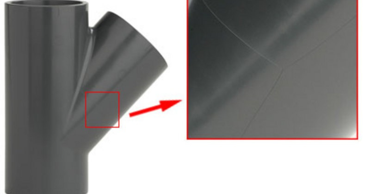
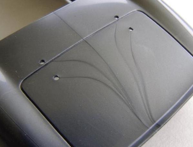
Finding flow lines in molded machined parts can be a persistent headache for manufacturers and engineers. These flow lines occur when two or more streams of molten plastic meet during the injection molding process and fail to fuse completely. They are also known as weld lines or knit lines. These lines can compromise the mechanical properties, aesthetics, and functionality of the final product.

If you are dealing with such a situation, don’t worry, it happens. Engineers have assigned some molding techniques and parameters to tackle this situation. Say goodbye to flow lines as we delve into the art of seamless injection molding, where every part emerges not only mechanically robust but also visually impeccable.
Enhancing Material Flow During Injection Molding
Material flow in injection molding orchestrates the transformation from molten resin to a precise, intricate part. Proper flow ensures even distribution, preventing defects like flow lines. To ensure there is no flow line in your design, these techniques should be implemented Specially for custom machined parts.
Cold Slugs and Wells
Sometimes, not all of the plastic material melts properly before entering the mold cavity. These unmelted bits are called cold slugs and they can cause problems by interrupting the flow of melted plastic and creating lines in the final product. To solve this issue, a useful solution is to have a special space called a cold slug well near the entry point of the mold, which acts as a storage area for these unmelted pieces.
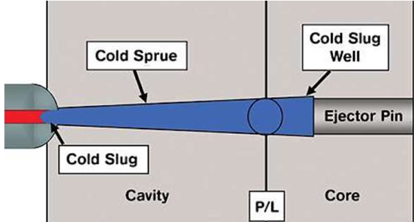
This way, the cold slugs are kept away from the final part of the product. A well-designed cold slug well not only inhibits the introduction of undesirable materials into the final part but also promotes smoother material flow. By minimizing interruptions caused by cold slugs, the manufacturing process can maintain a more consistent flow pattern, thus reducing the likelihood of flow lines in molding and cnc services.
Gates and Runners
The geometry of gates and runners significantly influences material flow dynamics. Wide gates and runners facilitate the unobstructed flow of molten plastic into the mold cavity. Inadequate dimensions in these channels can cause flow disruptions and promote the formation of flow lines.
Well-designed and appropriately sized gates and runners ensure an even distribution of material, preventing abrupt changes in flow direction that contribute to flow lines. By allowing the molten plastic to flow smoothly and uniformly, the risk of flow line occurrence is mitigated.

Nozzle-to-Mold Distance
The proximity between the hot nozzle and the mold cavity plays a crucial role in maintaining material temperature and viscosity during injection molding. Reducing this distance enhances material flow by minimizing the time the molten plastic is exposed to external cooling influences.
A shorter nozzle-to-mold distance helps sustain the desired temperature and viscosity of the material, preventing premature cooling and solidification that can lead to the formation of flow lines. This optimization ensures that the material maintains its flow characteristics until it fills the mold cavity completely.
Back Pressure
Manipulating back pressure during the injection process is an effective strategy for achieving a uniform melt and minimizing flow disruptions. By increasing back pressure, any inconsistencies or agglomerates in the material are broken down, resulting in a more homogenous melt. This homogeneity contributes to a smoother and more consistent flow pattern within the mold cavity, reducing the probability of flow line formation.
Adequate back pressure helps to maintain the material’s integrity as it flows, promoting optimal material distribution and overall part quality. The high quality parts , help in more smoother surfaces, and ensures less CNC services.
Increase Temperature and Injection Speed
One of the primary strategies to mitigate flow lines in injection molded parts involves carefully controlling the material’s temperature and injection speed. These factors play a crucial role in determining the material’s flow behavior and its ability to uniformly fill the mold cavity.
The temperature at which the plastic material is processed significantly influences its viscosity and flow characteristics. Elevating the material’s temperature within the appropriate processing range can have a notable impact on flow line reduction. Higher temperatures cause the polymer chains within the material to become more mobile and less viscous.
As a result, the material flows more easily, filling the mold cavity with improved uniformity. This increased flowability helps in preventing the formation of flow lines as the molten plastic can more effectively merge and fuse, resulting in a smoother machined Parts.
Rapid injection of the material ensures that it fills the mold cavity quickly, reducing the time during which cooling can begin. Flow lines are often formed when molten plastic starts to cool and solidify before filling the mold. By injecting the material at a higher speed, the molten plastic has less time to cool and solidify prematurely. This leads to a more consistent and uniform fill, minimizing the chances of flow lines. It’s important to note that the injection speed should be balanced with other process parameters to avoid issues like excessive shear heating or part distortion in custom machined parts.
Appropriate Materials for Smooth Flow
Selecting the appropriate material is a fundamental step in mitigating flow line formation during the injection molding process. The material’s viscosity and flow characteristics directly influence its ability to fill the mold cavity uniformly and avoid flow disruptions. High-viscosity materials, characterized by their resistance to flow, are particularly susceptible to the formation of flow lines. This is because their limited flowability can lead to incomplete fusion at the meeting points of molten material streams.
When choosing a material, it’s essential to consider its melt flow rate (MFR) or melt viscosity, both of which indicate how easily the material can flow when heated to its molten state. Materials with higher MFR values have lower viscosity and flow more easily, which can contribute to smoother material flow and reduced flow line formation in final CNC machined parts. It’s crucial to strike a balance between the material’s viscosity and other desired properties, such as mechanical strength, chemical resistance, and thermal stability.
Gate Locations to Avoid Flow Lines

Lastly position of Gates, the placement of gates plays a significant role in flow line prevention. Gates should be positioned in areas that allow the material to flow uniformly throughout the mold cavity. Avoid placing gates near corners or intersections, as these areas often experience flow disruptions and result in flow lines.
Instead, position gates strategically to ensure a balanced flow of material without abrupt changes in direction. A strategic gate placement further solidifies this battle, culminating in the production of impeccably crafted, high-quality machined parts.
Conclusion
Addressing flow lines in injection molded parts involves a combination of design considerations and process adjustments. By implementing strategies such as optimizing gate and runner designs, controlling material temperature and injection speed, selecting appropriate materials, and carefully positioning gates, manufacturers can significantly reduce the occurrence of flow lines and produce high-quality CNC machined parts.